

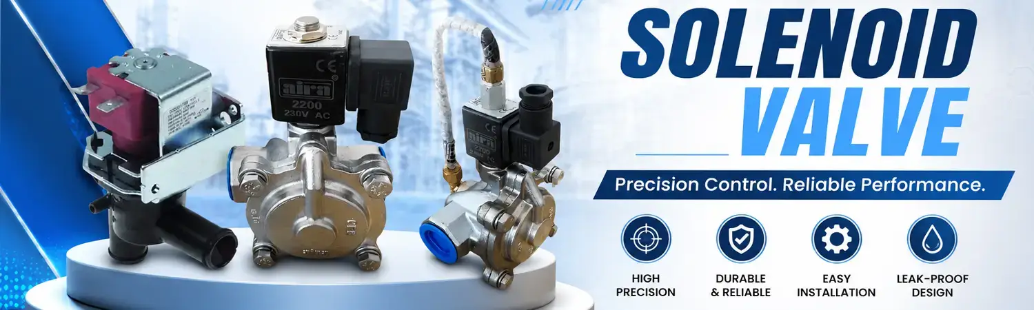
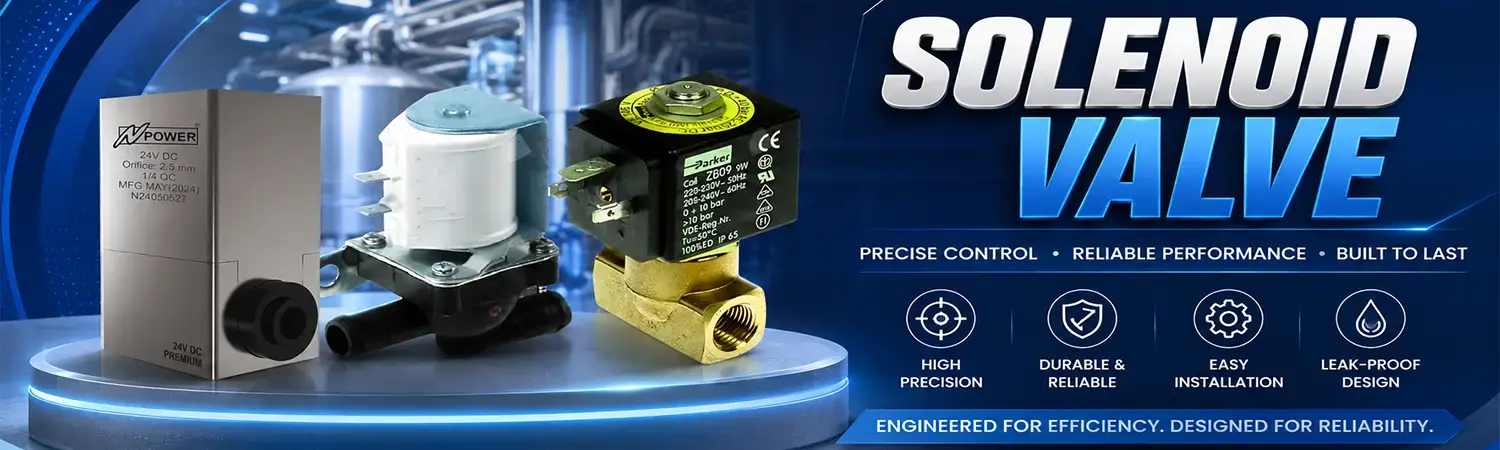
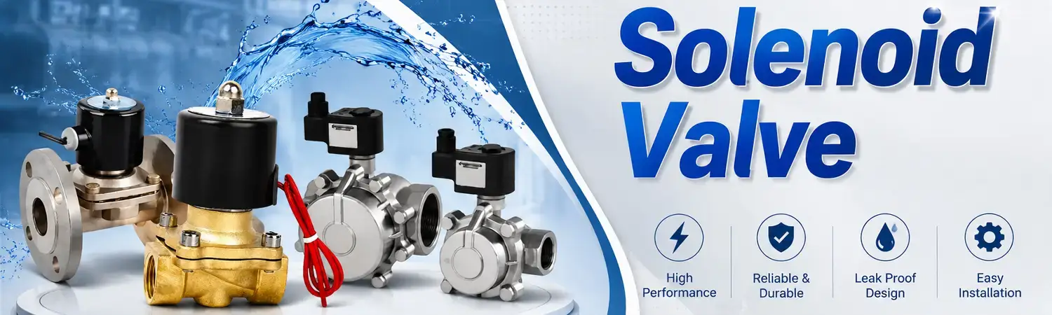
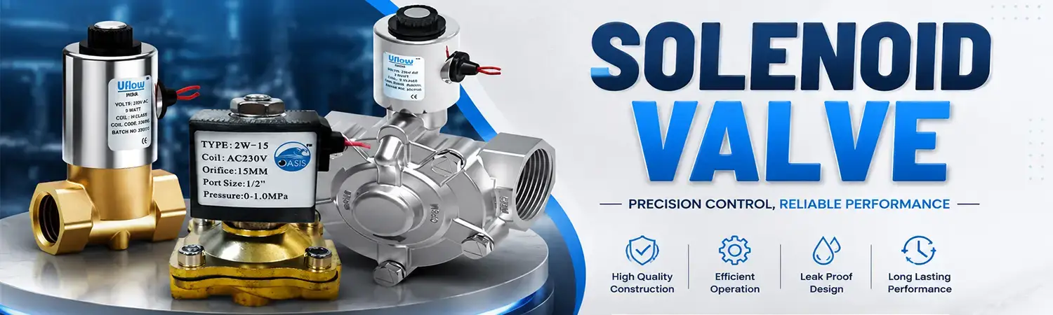
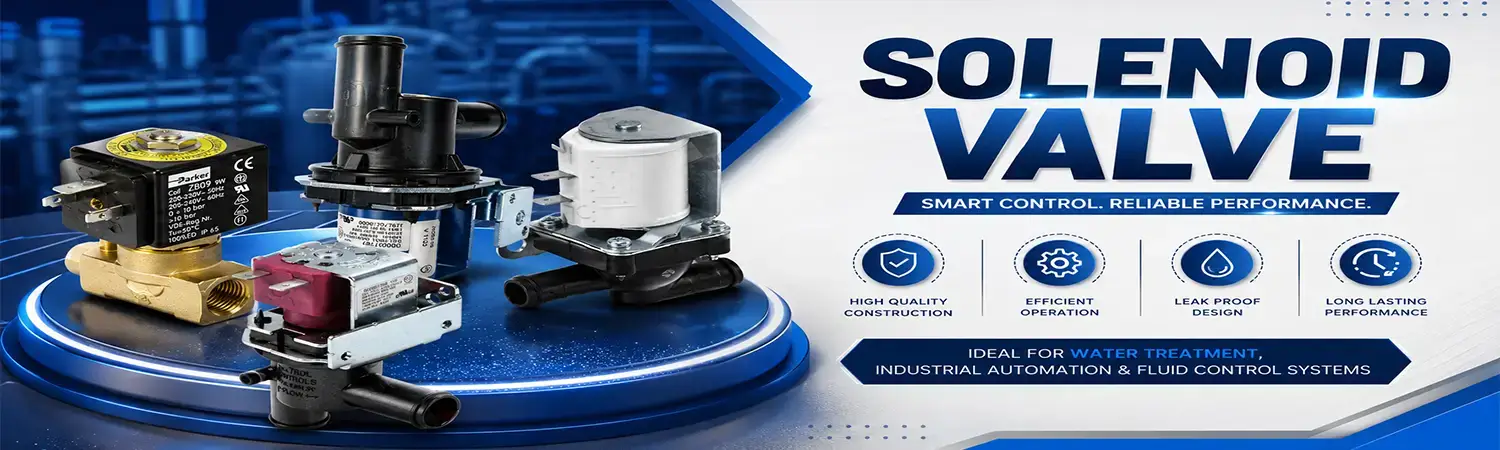
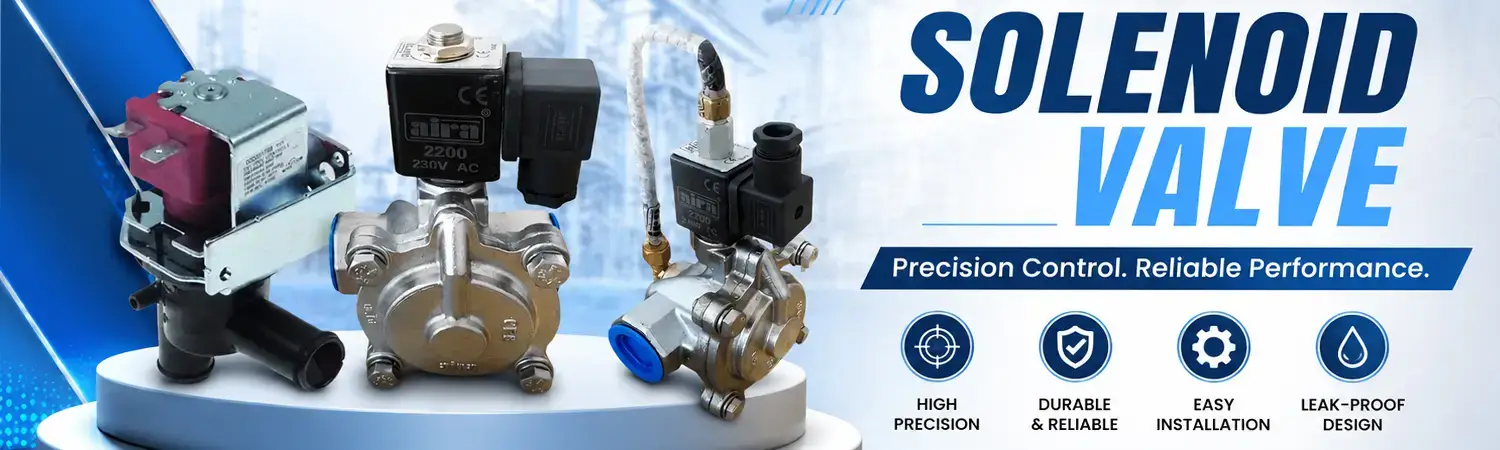
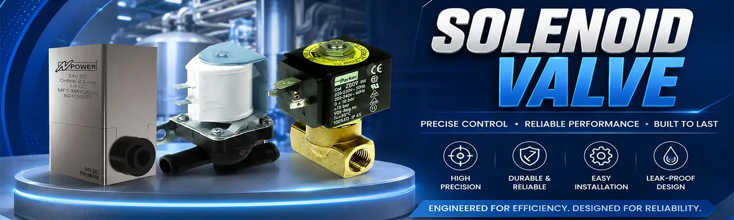
Industrial RO Solenoid Valve in Delhi


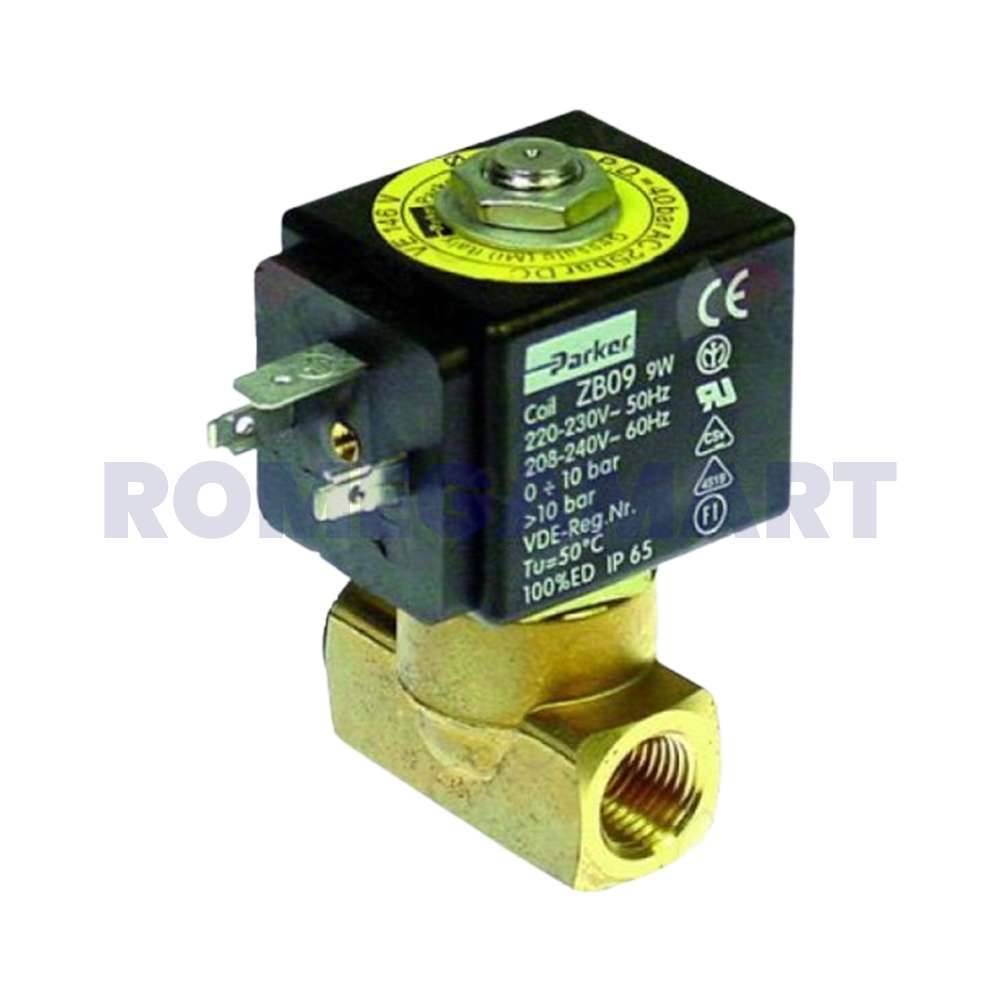


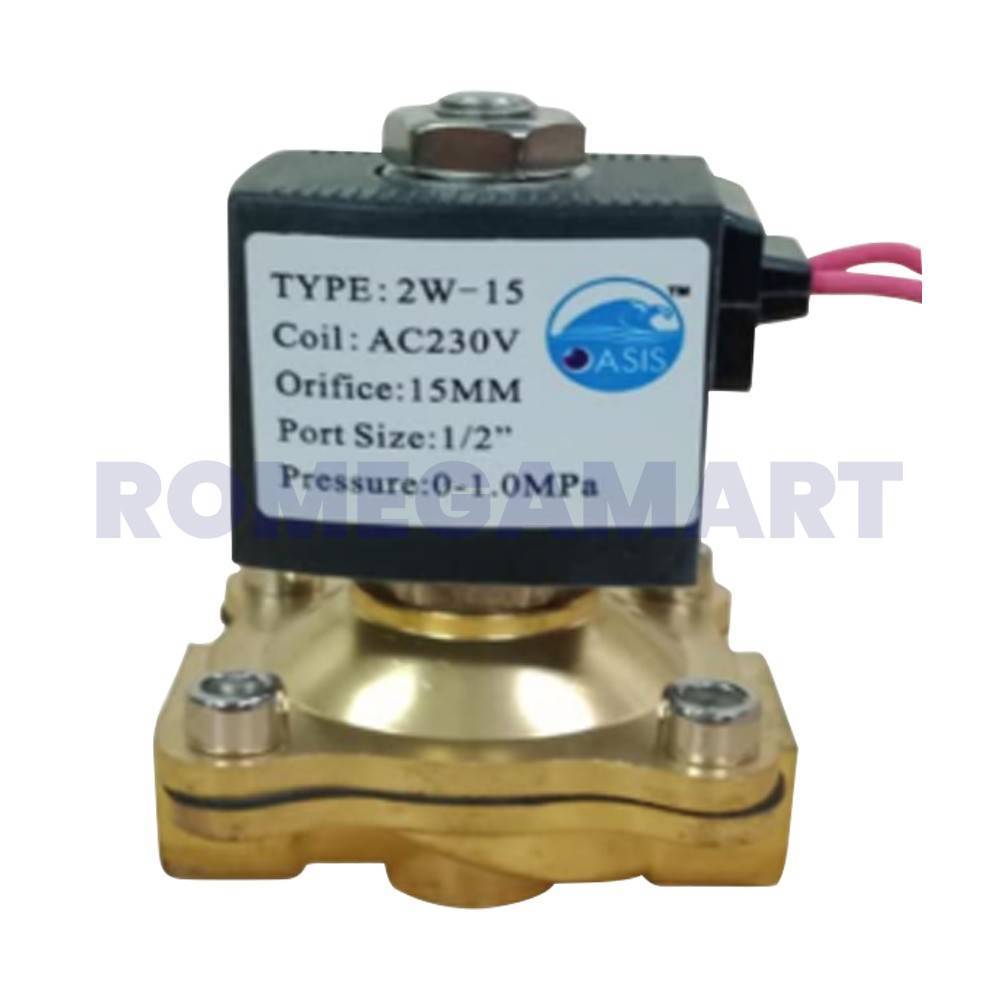


Solenoid Valve for Industrial Water Treatment and Automation
A solenoid valve is an electrically operated valve used to start, stop or redirect the flow of liquids and gases. It uses an electromagnetic coil to move an internal plunger, diaphragm or piston, allowing automated control without manual operation.
Solenoid valves are widely used in industrial RO plants, water purification systems, irrigation, HVAC equipment, pneumatic machinery, chemical dosing systems, compressors and process automation. Their quick switching, compact design and remote-control capability make them an important component in modern fluid-control systems.
For water treatment businesses, selecting the correct solenoid valve helps improve process reliability, reduce manual intervention and protect pumps, filters, membranes and other equipment.
What Is a Solenoid Valve?
A solenoid valve is an electromechanical flow-control device. When electrical power reaches the coil, it creates a magnetic field that moves the valve’s internal actuator. This movement opens or closes a flow passage.
When the power is removed, a spring or other return mechanism moves the valve back to its normal position. Depending on the model, the normal position can be open or closed.
A typical solenoid valve consists of:
Electromagnetic coil.
Plunger, armature or piston.
Valve body.
Valve seat and orifice.
Diaphragm, where applicable.
Return spring.
Seals and O-rings.
Inlet and outlet ports.
Electrical terminals or connector.
The valve body and seals should be compatible with the fluid, operating temperature, pressure and installation environment.
How Does a Solenoid Valve Work?
The solenoid valve working principle is based on electromagnetism:
The control panel, sensor or switch sends voltage to the coil.
Electrical current produces a magnetic field.
The magnetic field attracts the ferromagnetic plunger.
The plunger opens, closes or redirects the flow passage.
Fluid flow starts, stops or changes direction.
When power is removed, the return spring restores the normal position.
A direct-acting valve moves the main sealing element directly. A pilot-operated valve uses the solenoid to control a small pilot passage, while fluid pressure assists movement of the main diaphragm or piston. Direct-acting models can operate at zero or very low differential pressure, whereas pilot-operated designs typically require a minimum pressure differential
Types of Solenoid Valves
Direct-Acting Solenoid Valve
A direct-acting solenoid valve uses the coil to move the plunger directly against the fluid pressure. It does not depend on system pressure to open or close.
Best suited for:
Low-flow applications.
Low-pressure or zero-pressure lines.
Small water treatment systems.
Dosing and laboratory equipment.
Vacuum or specialised applications.
Direct-acting valves generally have smaller orifices than pilot-operated models because the coil must provide the force needed to control the flow directly.
Pilot-Operated Solenoid Valve
A pilot-operated solenoid valve uses system pressure to move a larger diaphragm or piston. The coil opens a small pilot port, creating a pressure difference that operates the main valve.
Best suited for:
Higher flow rates.
Pressurised pipelines.
Larger pipe sizes.
Industrial water systems.
Irrigation and process applications.
Pilot-operated valves can handle larger flow paths efficiently, but their minimum operating pressure must be checked before purchase
Semi-Direct-Acting Solenoid Valve
A semi-direct or assisted-lift solenoid valve combines features of direct-acting and pilot-operated designs. The coil assists the diaphragm or piston while the valve can operate with a lower pressure differential than many conventional pilot-operated valves.
Two-Way Solenoid Valve
A two-way solenoid valve has one inlet and one outlet. It controls flow by opening or closing a single passage.
Common uses include:
Water inlet control.
RO system automation.
Air compressors.
Irrigation lines.
Chemical dosing.
HVAC and refrigeration systems.
Three-Way Solenoid Valve
A three-way solenoid valve has three ports and can divert, mix or exhaust flow. It is commonly used for pneumatic actuators, single-acting cylinders, dosing systems and process switching.
Normally Closed Solenoid Valve
A normally closed, or NC, solenoid valve remains closed when the coil is de-energised. It opens when electrical power is applied.
This design is often selected where the flow should stop automatically during a power failure.
Normally Open Solenoid Valve
A normally open, or NO, solenoid valve remains open without power and closes when the coil is energised. It can be useful where continuous flow is preferred or where the fail-safe position requires the line to remain open.
The correct choice between NC and NO should be based on the safety requirements and failure response of the complete system.
Solenoid Valves in RO and Water Treatment Plants
Solenoid valves play an important role in the automation of water purification equipment. They can control the movement of raw water, filtered water, permeate, reject water, chemical solutions and cleaning fluids.
Common RO plant applications include:
Automatic raw-water inlet control.
Tank-level-based water supply.
RO membrane flushing.
Reject-water regulation.
Permeate-line control.
Filter backwashing.
Chemical dosing.
TDS-control systems.
UV and post-treatment isolation.
Automatic shutdown during low-water conditions.
A solenoid valve should not be selected only by pipe size. The flow rate, pressure range, fluid temperature, coil voltage, seal material, orifice size and operating cycle must also match the RO plant design.
Common Applications
Water Treatment
Solenoid valves automate filtration, backwashing, dosing, tank filling and membrane flushing in commercial and industrial water treatment systems. They may be used with control panels, level sensors, pressure switches and programmable controllers.
Irrigation
Water solenoid valves allow automatic opening and closing of irrigation zones. They can be controlled by timers, soil-moisture sensors or central irrigation controllers.
Industrial Automation
Solenoid valves operate pneumatic cylinders, air tools, actuators and automated machinery. Three-way, four-way and five-way configurations are frequently used for directional control.
HVAC and Refrigeration
Specialised solenoid valves regulate refrigerant, water and air circuits. The valve must be rated for the specific refrigerant, temperature and pressure conditions.
Chemical Dosing
Chemical-resistant valve bodies and seals can be used to control dosing solutions. Material compatibility is particularly important because incompatible seals may swell, harden or fail.
Food, Beverage and Pharmaceutical Systems
Stainless steel or sanitary solenoid valves may be selected for applications requiring cleanable surfaces and controlled contamination risk. The valve should meet the required hygiene, material and cleaning specifications.
Important Solenoid Valve Specifications
Fluid or Media Type
Identify whether the valve will control:
Water.
Air.
Oil.
Steam.
Gas.
Chemical solution.
Refrigerant.
Compressed air.
A valve designed for water should not automatically be used for steam, oil or aggressive chemicals.
Operating Pressure
Check the minimum and maximum pressure, including pressure fluctuations. Pilot-operated valves generally need a minimum differential pressure, while direct-acting valves are more suitable for low-pressure operation.
Flow Rate and Cv
The flow coefficient, commonly expressed as Cv, helps indicate the valve’s flow capacity. Select a valve that can meet the required flow without creating excessive pressure loss. A small amount of additional capacity may be useful, but oversizing can reduce control accuracy.
Port Size
Check the nominal port diameter, connection standard and thread type. The valve should match the pipeline and fittings without creating an unnecessary restriction.
Coil Voltage
Common coil options include:
12V DC.
24V DC.
24V AC.
110V AC.
220–240V AC.
The coil voltage must match the control system. Applying the wrong voltage can cause failure, overheating or unsafe operation.
Body Material
Common body materials include brass, stainless steel, engineering plastic and aluminium. Brass is common for general water and air applications, while stainless steel may be preferred for corrosive, high-temperature or hygienic environments.
Seal Material
EPDM, NBR, Viton, silicone and PTFE are used for different fluids and temperatures. Seal selection should be based on chemical compatibility, operating temperature and pressure.
Operating Temperature
Confirm the minimum and maximum media and ambient temperature. Steam and hot-water applications require valves specifically designed for elevated temperatures.
Duty Cycle
Determine whether the valve will operate occasionally or continuously. Continuous-duty applications require a coil designed to remain energised without excessive heating.
Protection Rating
For wet, dusty or outdoor installations, check the coil enclosure and connector protection rating. The required rating depends on the installation environment.
Solenoid Valve Selection Guide
Use this process when choosing a valve for an industrial system:
Identify the fluid and check chemical compatibility.
Record minimum and maximum operating pressure.
Calculate the required flow rate.
Select direct-acting, pilot-operated or semi-direct operation.
Choose normally open or normally closed operation according to the fail-safe requirement.
Confirm pipe size, connection type and flow direction.
Select the correct body and seal materials.
Match the coil voltage with the control panel.
Check temperature, duty cycle and environmental protection.
Confirm replacement coils, seals and service support are available.
For example, a low-pressure RO inlet line may require a 24V DC, normally closed, water-compatible valve. A large, continuously pressurised industrial pipeline may be better suited to a pilot-operated valve with a larger orifice and suitable pressure differential.
Installation Best Practices
Correct installation improves valve performance and reduces premature failure:
Check the flow-direction arrow on the valve body.
Install the valve in the orientation specified by the manufacturer.
Flush the pipeline before installation.
Remove dirt, welding residue and metal particles from the line.
Install a strainer where the fluid contains debris.
Confirm that the coil voltage matches the power supply.
Avoid using the coil as a lifting or holding point.
Provide adequate space for coil and valve servicing.
Use suitable sealant without allowing excess material to enter the passage.
Depressurise the line before removing the valve.
Test the valve for leakage after installation.
A line strainer is especially useful in water treatment systems because dirt can obstruct the orifice or prevent the diaphragm from closing correctly.
Common Problems and Troubleshooting
Problem | Possible cause | Recommended check |
|---|---|---|
| Valve does not open | No power, incorrect voltage or damaged coil | Check supply voltage, wiring and coil continuity |
| Valve does not close | Dirt on seat, damaged diaphragm or incorrect pressure | Clean the valve and verify pressure conditions |
| Coil becomes excessively hot | Wrong voltage, continuous-duty mismatch or restricted movement | Confirm coil rating and inspect the plunger |
| Low or restricted flow | Undersized orifice, blocked filter or low pressure | Check flow path, strainer and pressure |
| Valve leaks externally | Damaged O-ring, loose connection or cracked body | Inspect seals and connections |
| Pilot valve fails to operate | Insufficient differential pressure | Compare system pressure with the valve datasheet |
| Repeated coil failure | Moisture, overheating or voltage fluctuation | Check enclosure, electrical supply and operating cycle |
Do not open or service a pressurised solenoid valve. Isolate the electrical and fluid supplies before maintenance.
Benefits of Buying Quality Solenoid Valves
A correctly specified solenoid valve can provide:
Fast automatic switching.
Reliable remote operation.
Compact installation.
Reduced manual intervention.
Compatibility with PLC and control-panel systems.
Low routine maintenance.
Improved process consistency.
Easy integration with sensors and automation equipment.
Availability in different voltages, materials and port sizes.
For B2B buyers, product availability and spare-part support are also important. A supplier that can provide replacement coils, diaphragms, seals and complete valves can help reduce maintenance downtime.
Frequently Asked Questions
What is a solenoid valve used for?
A solenoid valve automatically controls the flow of liquids or gases. It is used in water treatment, RO plants, irrigation, HVAC, pneumatic equipment, chemical dosing and industrial automation.
Which is better: normally open or normally closed?
Neither is universally better. A normally closed valve stops flow when power is removed, while a normally open valve allows flow without power. Select the configuration that provides the safest failure response for your system.
Can a solenoid valve control water?
Yes. Water solenoid valves are available in brass, stainless steel and plastic bodies with different pressure, temperature, port and seal specifications.
Can a solenoid valve work at zero pressure?
Direct-acting valves can generally operate at zero or very low differential pressure. Pilot-operated valves usually require a minimum pressure difference, so always check the technical datasheet.
Why does a solenoid valve make a clicking sound?
A click usually occurs when the coil moves the internal plunger. A loud, repeated or irregular sound may indicate incorrect voltage, dirt, vibration, a damaged plunger or unstable power.
How long does a solenoid valve last?
Service life depends on fluid cleanliness, switching frequency, pressure, temperature, coil duty cycle, seal compatibility and maintenance. Correct sizing and clean operating conditions can improve service life.
Final Call to Action
Looking for a dependable solenoid valve for an industrial RO plant, water treatment system or automation project? Choose from suitable valve types, voltage options, materials and connection sizes for reliable flow control.
Explore Solenoid Valve Products



